The NmraDcc Arduino library can be found in the Arduino Library Manager or downloaded from here: https://github.com/mrrwa/NmraDcc/archive/master.zip
There are many ways to interface an Arduino to the DCC Track signal but here are a few methods I can recommend:
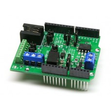
- Using the Arduino DCC Shield from Iowa Scaled Engineering
- Using Wolfgang Kuffer’s DCC Decoder circuit
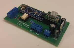
- Using the Model Railway DCC Turntable Accessory Decoder from DCC Interface
Iowa Scaled Engineering’s Arduino DCC Decoder Shield
I’ve recently started to use the Arduino DCC Decoder Shield from Iowa Scaled Engineering and it works really well.
It has a number of hardware configuration options for powering the project and which pins the DCC signal is on, which gives some flexibility and it also has the DCC ACK circuit for reading CVs.
My NmraDcc library fully supports this DCC Decoding interface and I can recommend using it.
The design is Open Hardware and is available on GitHub.
 DCC Interface’s Model Railway DCC Turntable Accessory Decoder for Arduino Nano
I’ve used the Turntable Accessory Decoder to drive a Stepper Motor and I written an article about that project. Ian Jeffery has other DCC Interface boards that look interesting too.
My NmraDcc library fully supports this DCC Decoding interface and I can recommend using it.
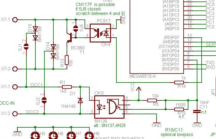
Wolfgang Kuffer’s DCC Decoder
This schematic is taken from one of Wolfgang Kuffer’s OpenDCC decoders. There are two parts to this circuit:
- The DCC Input signal comes in via the 6N136 fast optocoupler and is fed into one of the the AVR INTx pins. On an Arduino UNO this can be digital pin 2 or 3. The pin you use and the interrupt number need to be specified by calling the pin( uint8_t ExtIntNum, uint8_t ExtIntPinNum, uint8_t EnablePullup) method. This allows some flexibility with the various Arduino models.
- The DCC Service Mode (Programming Track) ACK circuit. This signal can be taken from any Arduino pin and needs to cause the DCC Decoder to increase the supply current by 60mA for 6ms. In the schematic below this is achieved by the PC817 (or similar) optocoupler. In this case it causes T1 (BC860) to conduct and cause the 100R resistor to be connected across the Bridge Rectifier formed by D14 + D15.

