Inspired by some of some of Geoff Bunza’s work, John Cornell used an Arduino Uno to control level crossing (grade-crossing) booms and LED flashers. The details of John’s project are described below.
The booms are controlled by small servo-motors. Occupation detection is done via a simple circuit using a small toroidal transformer to detect the DCC feed to the track, in a block extending either side of the crossing. The occupation detection circuit and the Arduino are powered directly from the track as well.
Details of the project are shown below – enjoy!
John Cornell
Arduino Sketch
// Example Level Crossing Control
// Version 1 John Cornell 2015
// Uses software servo Library
//

#include <Servo.h>

Servo gate1servo; // create servo object to control crossing gate 1
 //ASSUMPTION Gate is down at position 30 and up at position 120
Servo gate2servo; // create servo object to control crossing gate 2
 //ASSUMPTION Gate is down at position 30 and up at position 120
int sensor1 = 5; // IR sensor pin Assumption== Pin goes LOW when train detected

int led1 = 10; // Led 1 pin first alternating flasher
int led2 = 11; // Led 2 pin first alternating flasher
int led3 = 12; // Led 3 pin second alternating flasher
int led4 = 13; // Led 4 pin second alternating flasher
int gateposition = 120; // variable to store the servo gateposition


int gates_started = 0; // this says if the crossing is active
int flash_state = 0;
long flash_time = 0;
long flash_interval = 900; // time in milliseconds between alternating flashes


void setup()
{
 gate1servo.attach(3); // attaches the servo on pin 3 to the servo object
 gate2servo.attach(4); // attaches the servo on pin 4 to the servo object
 gate1servo.write(gateposition); //start assuming no train
 gate2servo.write(gateposition); //start assuming no train
 pinMode(sensor1, INPUT);

 pinMode(led1, OUTPUT);
 pinMode(led2, OUTPUT);
 pinMode(led3, OUTPUT);
 pinMode(led4, OUTPUT);
 digitalWrite(led1, LOW); // Start with all flashers off
 digitalWrite(led2, LOW);
 digitalWrite(led3, LOW);
 digitalWrite(led4, LOW);
 flash_time = millis(); // time since sketch started
}

void loop()
{
 if ((digitalRead (sensor1)==LOW)&& (gates_started==0)) {
 gates_started = 1;
 starting_sequence();
 }
 if (gates_started) flash_leds(); //gates are down continue flashing
 if ((digitalRead(sensor1)==HIGH)&&(gates_started==1)) { //Train has left
 ending_sequence();
 }
}

void starting_sequence() {
 long wait_time;
// flash_time = millis(); was this wrong?
 wait_time = millis()+3000;
 while (wait_time > millis()) flash_leds(); //flash before dropping gates
 for(gateposition = 120; gateposition>30; gateposition-=1) // goes from 120 degrees to 30 degrees
 {
 gate1servo.write(gateposition); // tell servo to go to gateposition in variable 'gateposition'
 gate2servo.write(gateposition); // tell servo to go to gateposition in variable 'gateposition'
 flash_leds(); // keep flashing leds
 delay(40); // waits 40ms to slow servo
 }
}

void ending_sequence() {
 for(gateposition = 30; gateposition<120; gateposition++) // goes from 30 degrees to 120 degrees
 {
 gate1servo.write(gateposition); // tell servo to go to gateposition in variable 'gateposition'
 gate2servo.write(gateposition); // tell servo to go to gateposition in variable 'gateposition'
 flash_leds(); // keep flashing leds
 delay(40); // waits 40ms to slow servo
 }
 gates_started = 0; // gates are open
 digitalWrite(led1, LOW); // flashers completely off
 digitalWrite(led3, LOW);
 digitalWrite(led2, LOW);
 digitalWrite(led4, LOW);
}

void flash_leds() {
 if (flash_time > millis()) return;
 flash_state = ~flash_state;
 digitalWrite(led1, flash_state); // Alternate flashers
 digitalWrite(led3, flash_state);
 digitalWrite(led2, ~flash_state);
 digitalWrite(led4, ~flash_state);
 flash_time = millis()+flash_interval;
}
Project Diagrams and Photos

Level Crossing Control – Schematic and Pin Connections
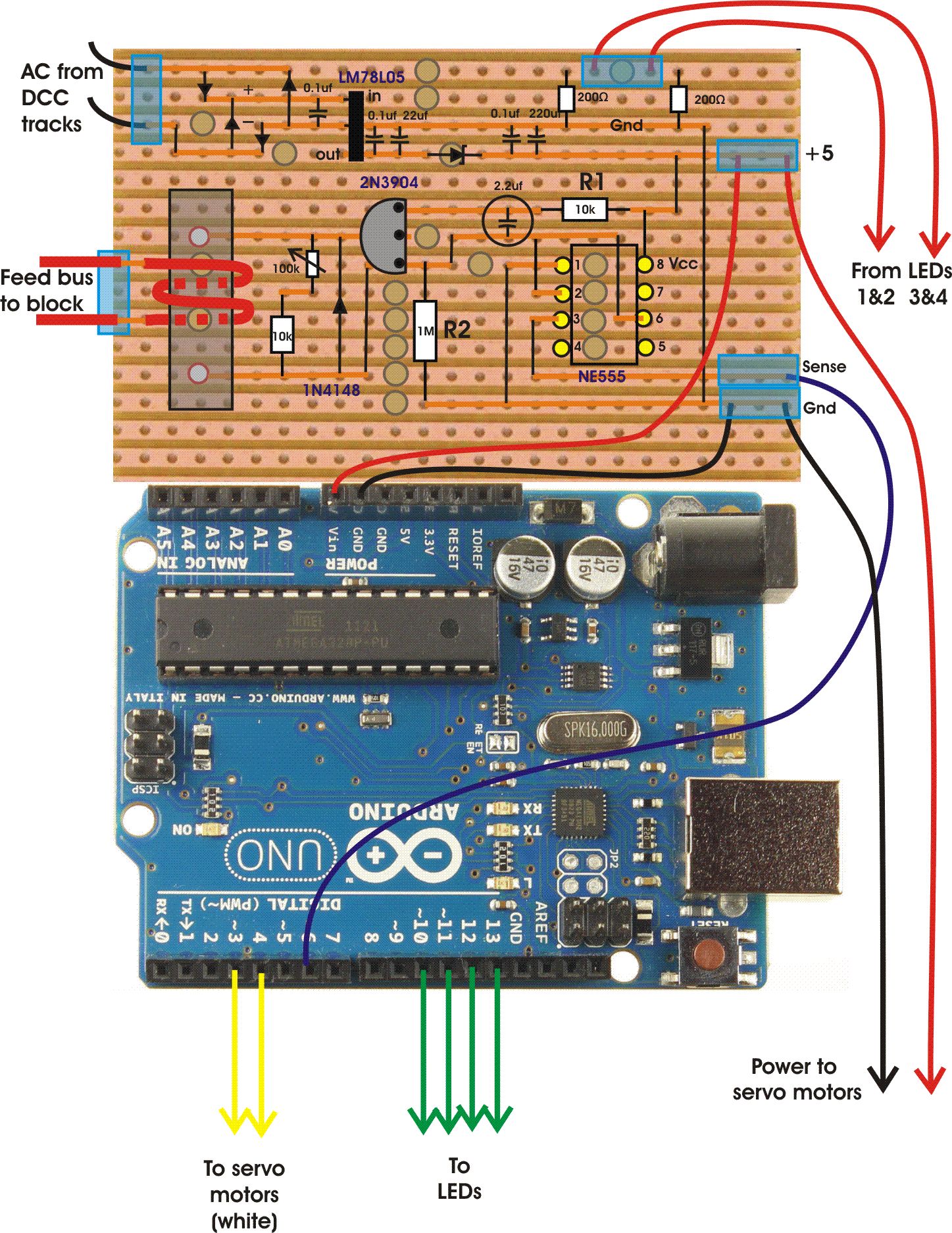
Level Crossing Control – Wiring Layout
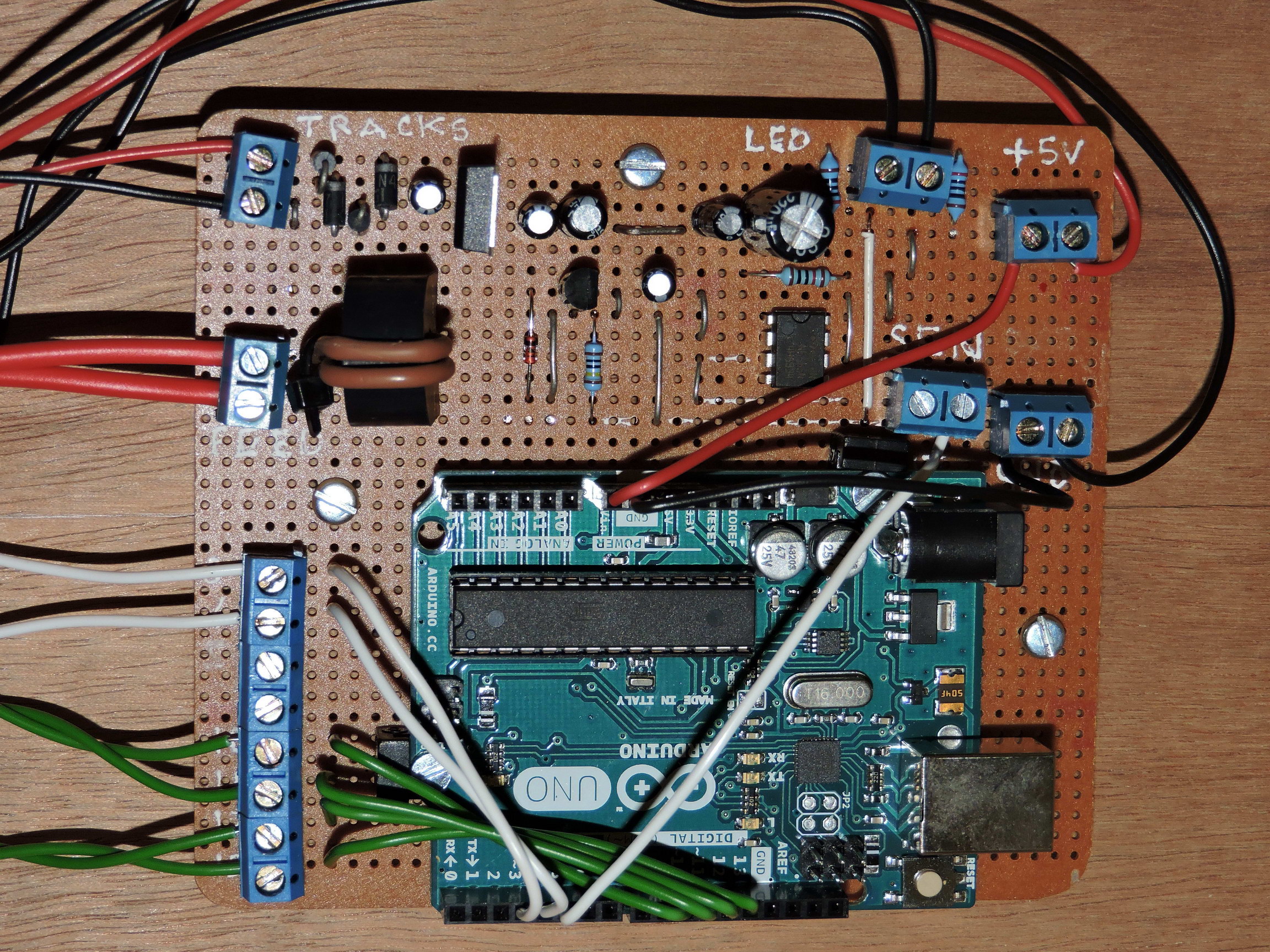
Level Crossing Control – Photo of the Completed Project